Home » Without Label » 480 Volt Motor Wiring - 480 Volt Motor Wiring Diagram - Wiring Diagram Networks : Control circuit until the start button is pressed once again.
480 Volt Motor Wiring - 480 Volt Motor Wiring Diagram - Wiring Diagram Networks : Control circuit until the start button is pressed once again.
480 Volt Motor Wiring - 480 Volt Motor Wiring Diagram - Wiring Diagram Networks : Control circuit until the start button is pressed once again.. Each part ought to be placed and connected with other parts in particular way. Factories and other industrial buildings sometimes require a higher voltage for their electrical service. 3 3 phase motor winding; L1 to t1, l2 to t2, l3 to t3, t4 to t7, t5 to t8 and t6. Always use wiring diagram supplied on motor nameplate for motors with thermal protection single voltage / single rotation single voltage / reversible rotation.
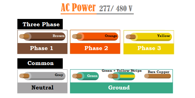
On both of these grounded On six lead single voltage motors watch out and check the manufacturer diagrams. 277v is a standard single phase voltage derived from 480v three phase voltage system available in commercial applications. Three phase wiring diagrams always use wiring diagram supplied on motor … White 5 4 1 3 2 ts bs blue bge red vac ac.
480 Volt 3 Phase Motor Wiring Diagram - Wiring Diagram ... from www.mikrora.com Factories and other industrial buildings sometimes require a higher voltage for their electrical service. Make the specified connections and secure the terminals in place. Those nine leads provide an option for supplying power from either high or low voltage sources. High motor voltage, the motor is powered by an inverter, or electronic soft start. To add an additional remote station wire the new stop button in series with the. Most use the high voltage wiring diagram only. 480v 3 phase motor wiring diagram effectively read a cabling diagram, one has to learn how typically the components in the system operate. Three phase wiring diagrams always use wiring diagram supplied on motor …
I have a 20 hp hyundai dual voltage 240/480 3 phase motor im wiring up.
For specific leeson motor connections go to their website and input the leeson catalog # in the review box, you will find connection data, dimensions, name plate data, etc. 220/380v motor motor wired 380v brake voltage 380v bg or bge brake rectifier brake rectifier brake rectifier. Electric motor wire marking & connections. Otherwise, the arrangement will not work as it ought to be. On six lead single voltage motors watch out and check the manufacturer diagrams. Each part ought to be placed and connected with other parts in particular way. 480v 3 phase 6 lead motor wiring diagram. Make the specified connections and secure the terminals in place. Always use wiring diagram supplied on motor nameplate for motors with thermal protection single voltage / single rotation single voltage / reversible rotation. The coil is energized by the 120v, and the pushbuttons or other control devices operate at this same. High motor voltage, the motor is powered by an inverter, or electronic soft start. 4 3 phase motor winding resistance values chart. L1 to t1, l2 to t2, l3 to t3, t4 to t7, t5 to t8 and t6.
480v 3 phase delta is a 3 wire power configuration and does not include a neutral wire. I have a 20 hp hyundai dual voltage 240/480 3 phase motor im wiring up. You should have a fully functional three phase motor at this time. But at least one (toshiba) does not. 2.1 motor ohm values chart;
480 Volt 3 Phase 6 Lead Motor Wiring Diagram - Wiring Diagram from www.azom.com Most use the high voltage wiring diagram only. Wire a three phase motor in either a wye configuration or a delta configuration in high or low voltage using a nine lead set up. On six lead single voltage motors watch out and check the manufacturer diagrams. For specific leeson motor connections go to their website and input the leeson catalog # in the review box, you will find connection data, dimensions, name plate data, etc. 2.1 motor ohm values chart; The transformer's secondary provides 277v single phase and 480v single phase and three phase voltage levels. You should have a fully functional three phase motor at this time. L1 to t1, l2 to t2, l3 to t3, t4 to t7, t5 to t8 and t6.
The coil is energized by the 120v, and the pushbuttons or other control devices operate at this same.
Some work, some do nothing, some destroy it. 480v 3 phase 6 lead motor wiring diagram. Factories and other industrial buildings sometimes require a higher voltage for their electrical service. The transformer's secondary provides 277v single phase and 480v single phase and three phase voltage levels. Wire a three phase motor in either a wye configuration or a delta configuration in high or low voltage using a nine lead set up. Site this is images about 3 phase 6 lead motor wiring diagram posted by ella brouillard in 3 category on may 19 2019. 2 pole 3 wire 125vac wiring diagram indicating contact position eaton arrow hart 7. 3 3 phase motor winding; This video will show you how to wire up a 9 wire 3 phase motor to a 480 volt system.watch till the end for my tech tip.if performing on site, be sure to powe. 6 2010 dr motor common connection diagrams important notes 2 important notes. Current values in this chart are approximate, and are compiled from data published by several motor manufacturers. Control circuit until the start button is pressed once again. Electric motor wire marking & connections.
White 5 4 1 3 2 ts bs blue bge red vac ac. To add an additional remote station wire the new stop button in series with the. Wire a three phase motor in either a wye configuration or a delta configuration in high or low voltage using a nine lead set up. 480v 3 phase motor wiring diagram effectively read a cabling diagram, one has to learn how typically the components in the system operate. W2 cj2 ui vi wi
480 Volt 3 Phase Motor Wiring Diagram - Wiring Diagram ... from electricalfundablog.com The coil is energized by the 120v, and the pushbuttons or other control devices operate at this same. So the friend keeps watch and enjoy it. This might result in unexpected motor failures when critical services from such motors are required affecting availability of plants. Otherwise, the arrangement will not work as it ought to be. 4 wire 480 volt plug wiring diagram disclaimer. 2 it's a very easy way here to know the motor ohm values chart & set up the coil size of the motor. 3 3 phase motor winding; Most 480v power systems are not a delta configuration because the phase to ground voltage is 480v or above 300v.
L1 to t1, l2 to t2, l3 to t3, t4 to t7, t5 to t8 and t6.
This video will show you how to wire up a 9 wire 3 phase motor to a 480 volt system.watch till the end for my tech tip.if performing on site, be sure to powe. Actually voltage or current unbalance will produce too much heat thus damaging the motors. The coil is energized by the 120v, and the pushbuttons or other control devices operate at this same. Motor hp, amps and wire/conduit size table. 220/380v motor motor wired 380v brake voltage 380v bg or bge brake rectifier brake rectifier brake rectifier. Site this is images about 3 phase 6 lead motor wiring diagram posted by ella brouillard in 3 category on may 19 2019. This calculator will also give you motor amps and recommended breaker size, starter size, heater size and conduit size. The transformer's secondary provides 277v single phase and 480v single phase and three phase voltage levels. You should have a fully functional three phase motor at this time. So the friend keeps watch and enjoy it. Replace the cover on the motor and turn on the power. To add an additional remote station wire the new stop button in series with the. Most 480v power systems are not a delta configuration because the phase to ground voltage is 480v or above 300v.